In building the Upstairs Train, I ran into a number of problems and challenges due to its size and complexity. I pass on to you the lessons I learned in the hope that they will save you some time, frustration, and possible damage to your trains. These lessons fall into the following categories:
1. Preventing derailment when a switch is flipped the wrong way.
2. Independently running more than one train at a time in different "zones" when their tracks are interconnected.
3. Running a train in "mainline" mode through two or more zones.
4. Running more than one train around a single loop controlled by semaphores.
5. Preventing an engine from reversing directions after it has been stopped.
6. Designing a control panel that helps the operator keep it all straight.
After you read all that, read through this Summary, which ties it all together.
Fiber pins, then, can serve three different purposes: preventing derailment, independent operation in zones, and running multiple trains in a loop. If you keep these purposes separate in your mind, you can set up a very complex layout without getting confused, even when a single fiber pin serves two or three different purposes!
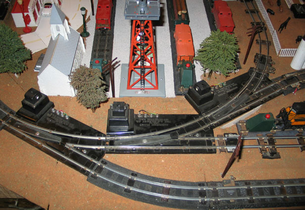
To summarize all this with an example, let's use the four lines coming into the Central Exchange (zone 1), as shown in this picture:.

The second line is the red downslope coming from the upper loop (zone 2). Since it is on the green leg of one switch and the red leg of another, it has a fiber pin in each rail to prevent derailment. The one on the white rail also serves as the zone boundary.
The third line is the green line of the lower loop (zone 4). Since it is on the green leg of one switch and the red leg of two others, it has a fiber pin in each rail to prevent derailment. The one on the white rail also serves as the zone boundary.
The top line is the red line of the lower loop (zone 4). Since it is on the red leg of all three switches, it needs only a fiber pin in the outside (black) rail to prevent derailment. But it also needs a fiber pin in the white pin as a zone boundary. This is where I made the mistake of putting the fiber pin two tracks in like the one on the black rail; as a result, the stopped train is powered by the wrong transformer. I had to move it.
The semaphore connection here will be interesting. A single semaphore will be able to control all four incoming lines. I will connect the semaphore's power source in the first section of track beyond the third (leftmost) switch and isolate its black rail with a fiber pin. Each of the top three incoming tracks already has a fiber pin in its black rail to protect from derailment; that pin can do double-duty as the start oif the isolated section of track required by the semaphore. I'll just have to add one to the black rail of the yellow line, two sections of track in from the switch. Think about it: that means a train on one of those four tracks can move forward only if the semaphore is green AND the switches are all flipped in its direction.
With all that said, here's what I'll be able to do once I get Lockout Eliminators and Semaphores everywhere I need them. With all four transformers on, one train will be going around the upper loop. When another train comes up the red upslope, it will pass out of zone 1 and stop just sort of a collision before the switch that allows it to enter the back side of the upper loop; when the train on the upper loop is away from that switch, I can flip it so that train will stop just short of collision the next time it comes around the loop to that switch. In the meantime, the train on the upslope proceeds up into the upper loop (zone 2) where I can direct it down the yellow slope to zone 3 and flip both switches so the train on the upper loop proceeds on its looping journey, all without touching any of the transformers.
At the same time, two trains can be approaching the Central Exchange, one from the yellow line from the Northeast Corner (zone 3), and another from the red or green line of the lower loop (zone 4). One passes through the switch and the other stops until the first is out of the way and I flip the switch. The same kind of thing happens at each switch where trains come together from two zones, all without touching a transformer.
In the process, it is possible to end up with two trains on the lower loop route through Union Station, or three trains are on the outer loop (up the red upslope and down the yellow slope). If one train is faster than the other, the semaphores prevent it from catching up with the other and causing a rear-end collision. (Until I get all the semaphores and hook them up, I'll have to rely on speed control using the transformers.)
Trains Engines Operating Accessories Bridges Towers Buildings
Crossings Construction Landscaping Lighting Semaphores Control Panel
Wish List History Useful Links

