In building the Upstairs Train, I ran into a number of problems and challenges due to its size and complexity. I pass on to you the lessons I learned in the hope that they will save you some time, frustration, and possible damage to your trains. These lessons fall into the following categories:
1. Preventing derailment when a switch is flipped the wrong way.
2. Independently running more than one train at a time in different "zones" when their tracks are interconnected.
3. Running a train in "mainline" mode through two or more zones.
4. Running more than one train around a single loop controlled by semaphores.
5. Preventing an engine from reversing directions after it has been stopped.
6. Designing a control panel that helps the operator keep it all straight.
After you read all that, read through the Summary, which ties it all together.
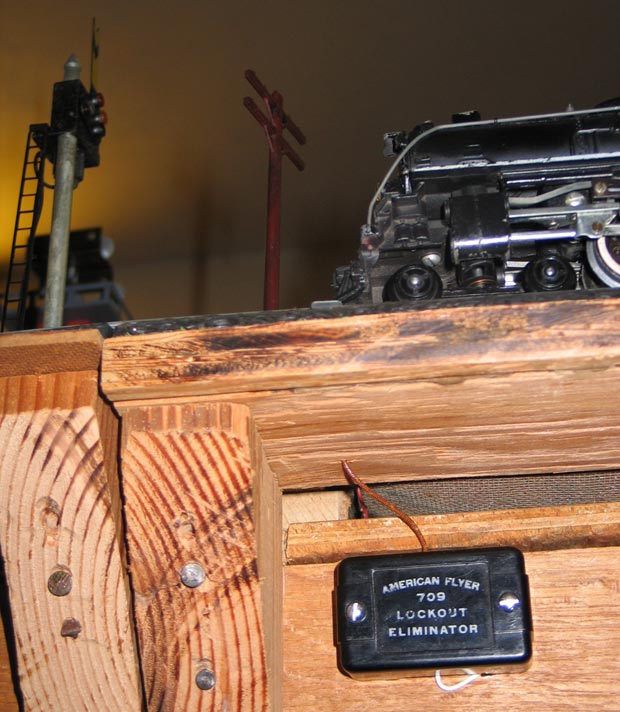
All these various lessons learned prevent derailment at switches, controls the operation of the trains in Zone Mode, and prevents rear-end collisions. But they introduce a little inconvenience. When a train loses power and stops, the reversing unit kicks in. When the condition that forced the train to stop is cleared, the train reverses direction. To prevent that from happening, I have started installing a #706 Lockout Eliminator at each such section of track. That keeps a low level of power to the engine, enough to prevent the reversing switch from kicking in, but not enough to allow the train to move. So when the switch flips, or the next transformer kicks in, or a semaphore clears a block, the train proceeds forward without reversing.
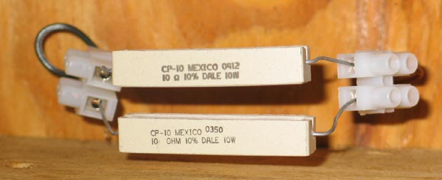
SIDE NOTE: Tom Barker's book American Flyer S Guage Operating & Repair Manual says you can use a 10 ohm 10 watt resistor instead of the more expensive Gilbert Lockout Eliminator. I found such a resistor at Radio Shack (#271-132) at two for $1.79 in May, 2005, and they work great. To finish my layout and add semaphores, I needed 14 more and $12.53 each sounded a lot more attractive than $140.00 plus shipping! Here's what they look like. (I use cut up barrier strips exetensively to connect things.)
If the isolated rail is the white rail, you have several choices. Connecting the Lockout Eliminator to the fixed power post of the transformer enables you to turn off the variable power, or even to use it to power a different train in the zone, without causing that first train to lose power and reverse directions. If you have a small number of trains, that may work well for you. But I have fourteen trains on the tracks and generally leave most of them parked in an isolated track; I'd rather not have all my engines powered all the time. And the reversing unit would cycle every time I turn the transfomer off. So I connect the Lockout Eliminator either to the variable power post of the transformer or to the white rail in a section of track before the isolated track.
The other choice you have is when the block is at the boundary of a zone. You can connect the Lockout Eliminator to the transformer that controls the zone the train is leaving, or to the one that controls the zone the train is entering. I chose to connect it to the zone the train is leaving because that one always has power and the engine won't reverse directions. (If didn't have power, the train couldn't have entered the block!)
That brings us back to the comment I made above: "when you have a switch at the boundary of a zone, as I do, you want the fiber pin at the switch, not two track lengths before the switch as you do to avoid derailment." The reason for this is that I want the Lockout Eliminator powered by the transformer that controls the zone the train is leaving, not to the one that controls the zone the train is entering. The choice is arbitrary, but I find that it usually works out better this way when you're running several trains around the layout.
I suggest you next read the Summary that ties together all these Lessons Learned about the control of multi-train operations.
It takes time and money to maintain a website like this. If you would like to contribute financially to its ongoing success, you may send a contribution via PayPal using theupstairstrain@yahoo.com as the payee. Both credit card and direct transfers would be gratefully appreciated.
Trains Engines Operating Accessories Bridges Towers Buildings
Crossings Construction Landscaping Lighting Semaphores Control Panel
Wish List History Useful Links

