In building the Upstairs Train, I ran into a number of problems and challenges due to its size and complexity. I pass on to you the lessons I learned in the hope that they will save you some time, frustration, and possible damage to your trains. These lessons fall into the following categories:
1. Preventing derailment when a switch is flipped the wrong way.
2. Independently running more than one train at a time in different "zones" when their tracks are interconnected.
3. Running a train in "mainline" mode through two or more zones.
4. Running more than one train around a single loop controlled by semaphores.
5. Preventing an engine from reversing directions after it has been stopped.
6. Designing a control panel that helps the operator keep it all straight.
After you read all that, read through the Summary, which ties it all together.
Zone Mode: Independently running more than one train at a time
The Upstairs Train comprises four separate and independently controlled "zones" as described in the Grand Tour. When a train leaves one zone and enters another, control over it passes from one transformer to another. That transformer controls its entry into the zone and controls its movement until it reaches the boundary of another zone. I can, in theory at least, turn on all four transformers so four trains move at once, from one zone to another around the layout. All I have to watch out for is one train catching up to another and rear-ending it. But, like most things in life, there's more to it than that.
My first layout as a kid was a simple loop with switches at one end to create two parallel tracks for my two trains. For that simple layout, the "two train operation" setting on each switch was sufficient to let me control the trains independently, running one at a time. But when I created the far more complex layout of The Upstairs Train, I found that when I turned on one transformer, two or three trains moved.
To figure out what was causing the problem, I followed each rail in each direction from a train to the nearest power source. With such a complex layout, all the combinations were mind-boggling! I resorted to reading my old Gilbert manual. Can you believe that? After fifty five years, I finally opened the manual. Incredible.
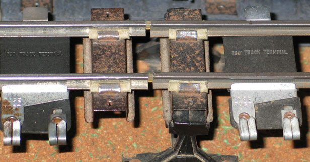
Anyway, the manual tells you three things you have to do to wire a layout for separate zones (on layouts simpler than mine). First, you need to isolate the zones electrically using insulating track pins. The picture below shows what the fiber pins look like. Use them in place of the metal track pins that conduct electricity from one track section to the next. They insulate the rails to prevent electrical contact.
The pins you buy today are plastic, not fiber. People still call them fiber pins because the original pins made by Gilbert were made of a fiber material. If you do find and use the original fiber pins, be careful when handling them and when you handle the track after they're inserted. They break very easily. The new plastic ones bend a lot more before breaking. An inexpensive makeshift alternative is flat toothpicks shaved down to fit, but they break easiest.
I bought some and tried it out. That solved most of the problems, but there were still a few special cases where two trains would move at once. I went back to tracing rails to every possible power source. The final solution was that certain sections needed insulating pins on BOTH rails, not just one. I finally got it working correctly.
It took me a while, but I finally figured out the principle behind it. I had to divorce the concept of multiple zone operation from the two-train operation of switches and fiber pins to prevent derailing at switches. That was difficult for me because those first two things had solved most of the problems I had had with multiple zone operation. Here are the elements of the principle underlying multiple zone operation:
The base posts of all the zone transformers are common. You do not need to isolate the rail that is connected to the base post (commonly called the "base rail"). You may need to isolate it with a fiber pin to avoid derailment, or to operate a semaphore, but you don't need to isolate it for multiple zone operation. If you need to do that, of course, it would mean that the base rails are not really common - the insulating pin prevents that. So the second thing the manual tells you to do is to wire the base posts of the transformers together just to make sure they really are common. At first, I didn't realize how significant that was and it gave me a lot of trouble. One day I pushed the button to blow the whistling billboard and a semaphore flipped instead! Believe me when I say it took a long time to figure that one out.
That brings us to the third thing the manual tells you to do. Since the base rail is common, the transformers need to be "in phase." To check whether they are, simply touch one end of a wire to the fixed 15V post of one transformer and the other end to the fixed 15V post of the other transformer. If you get a big spark, they are not in phase. To get them in phase, simply turn around the plug of one transformer in the electrical outlet; test it again and you will see that there is no spark. Tip: Unless you leave them plugged in all the time (which you would do if you have them on a surge protector - another tip!), you should mark the plugs somehow to make sure you plug them both in the same way next time.
It is the rail connected to the variable post of the transformer that must be isolated. (I call it the "white rail" because the convention is to use white wire for the variable post). Put a fiber pin in the track at the boundary of the zone. Note that when you have a switch at the boundary of a zone, as I do, you want the fiber pin at the switch, not two track lengths before the switch as you do to avoid derailment. The reason for this will become clear when we discuss reversing directions. That's something I didn't do correctly at first and had to change it.
Like many other things in layout design, however, you can't always put the pin at the switch because you may need a pin three sections in to prevent derailment. A pin at the switch defeats this. In taht case, the pin three sections in serves both purposes.
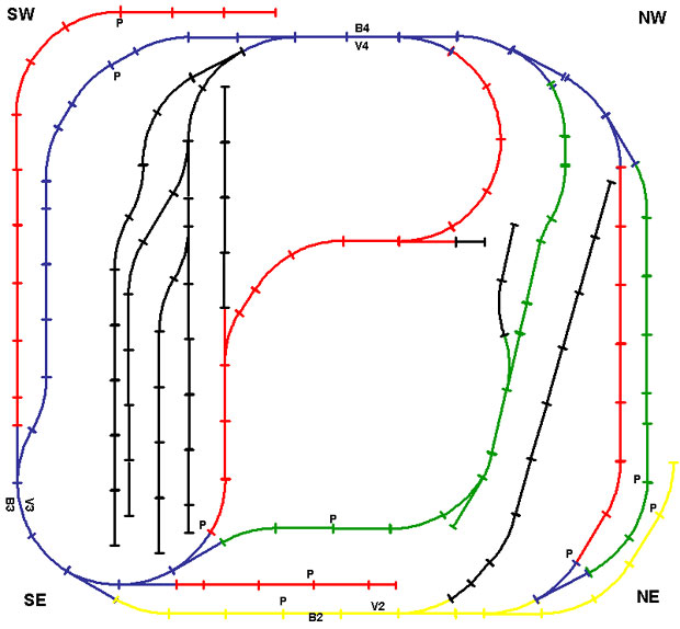
The following diagrams show where I put the pins to isolate the zones. Each P indicates a fiber pin; the side of the track it is on indicates which rail it insulates. P on both sides means both rails have pins. The first diagram shows the upper level and the slopes up and down. The second shows the lower level. All the pins are shown on both diagrams; there is no pin on one that is not also on the other. I separated the diagrams to avoid confusion between the overlapping upper and lower loops..
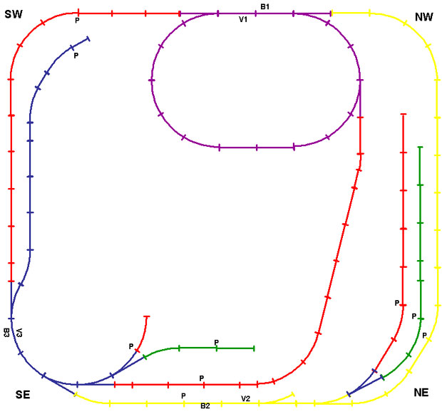
1. The Upper Loop around the hill (shown in purple on the track diagram above) and the yellow and red downslopes from it. To prevent derailment, it also includes the last three sections of track in the red upslope.
2. The Northeast Corner ("NE") around Union Station apears in both diagrams. It encompasses: the middle of the yellow line; the station siding; and the last few sections of the yellow downslope and Union Station green line (preventing derailment).
3. The Central Exchange (the Southeast "SE" Corner in blue), where four lines come together and split out to either the upper loop or the lower loop, also apears in both diagrams. It encompasses: the Central Exchange itself; most of the red upslope; the blue line entrance to the lower level; and the last few sections of the yellow line, the red downslope, and the lower level green line (preventing derailment).
4. The fourth zone is shown only in the lower diagram. It is the tunnel area of the Lower Loop (the blue along the west side) plus the rail yard (in black) and four alternate routes (red and green) around the lower level (including the red and green lines through Union Station). To prevent derailment, it also includes the last three sections of track in the Zone 3 entrance to the Lower Loop.
Running a train in "mainline" mode through two or more zones
Mainline Mode electrically combines two or three zones and enables the left side of the big #18B transformer to control movement through those zones as if they were a single zone. For example, a train can start at the Central Exchange (zone 1), ascend the Red Upslope to the Upper Loop (zone 2) and descend the Yellow Downslope to the Northeast Corner (zone 3) and back to the Central Exchange (zone 1) where it started.
The left side of the big #18B transformer powers the Central Exchange. Base Post power is provided at B3 in the SE corner, and variable power at V3, using a #690 Track Terminal.
I implemented Mainline Mode by switching the power source of each of the other three zones between its transformer and the left side of the big #18B transformer using a SPDT (single-pole double throw) switch I got at Radio Shack.
The Upstairs train has four alternative Mainline Routes, the first two of which have two sub-routes each:
1. By flipping only the switch for the Lower Loop, I can run a train from the Central Exchange around the red or green line of the Lower Loop and still operate trains in the Upper Loop or Northeast Corner independently. The variable power pole of the left side of the big #18B transformer connects to one throw of this switch and the variable power pole of the right side connects to the other throw. The pole connects to the track in the tunnel as indicated by V4 on the lower diagram above; Base Post power is provided at B4, both using a #690 Track Terminal. (I have not yet connected the Lower Loop semaphore; this may move.)
2. By flipping the switches for the Lower Loop and Northeast Corner, I can run a train from the Central Exchange into the Lower Loop, through either side of Union Station, and back the yellow line to the Central Exchange. Another train can be going around the Upper Loop. As with the Lower Loop SPDT switch, the variable power pole of the left side of the big #18B transformer connects to one throw of the Northeast Corner switch and the variable power pole of the 8B transformer connects to the other throw. The pole connects to the yellow line as indicated by V2 on the lower diagram above. Base Post power is provided at B2. The reason they are separated has to do with the semaphore in the Northeast Corner.
3. Alternatively, I can flip the switches for the Upper Loop and Northeast Corner to run a train up the red slope to the Upper Loop, down the Yellow Slope to the Northeast Corner, and back to the Central Exchange while independently making up a train in the railyard or moving a train into Union Station. The SPDT switch for the Upper Loop is wired like the others, to the left side of the #18B and the 4B, and out to the Upper Loop at V1, with Base Post power at B1. As with the Northeast Corner, they are separated because of a semaphore.
4. Finally, I can flip only the switch for the Upper Loop to run a train up the red slope to the Upper Loop and down the red downslope to the Central Exchange while independently making up a train in the railyard or moving a train into Union Station.
Next, I suggest you read the discusion on running more than one train around a single loop controlled by semaphores.
It takes time and money to maintain a website like this. If you would like to contribute financially to its ongoing success, you may send a contribution via PayPal using theupstairstrain@yahoo.com as the payee. Both credit card and direct transfers would be gratefully appreciated.
Engines Operating Accessories Bridges Towers Buildings
Crossings Construction Landscaping Lighting Semaphores Control Panel
Wish List History Useful Links The Gilbert Gallery

